
How to Read a Glue-Up Diagram: From Strips to a Finished Board
A glue-up diagram reads top to bottom as a sequence of steps: strips of one species glue into a panel first (the first glue-up), then the panel gets crosscut into slices of a set thickness, and those slices are arranged into rows for the final glue-up, with some rows flipped or mirrored to build the pattern.
The first time you look at a printed glue-up diagram, it is easy to get lost: panels, slices, rows, flip and mirror arrows everywhere. In practice there are only two operations, repeated as many times as the pattern needs, and once the order clicks the diagram reads in under a minute before you even turn on the saw.
First pass: strips into a panel
Everything starts with strips, boards of one thickness and species, stood on edge and glued face to face into a flat panel. This is where the species order gets decided, and that layout is what sets the color pattern of the finished board. The panel comes out wider than the sum of the strip widths on purpose: it already includes an edge trim allowance, so the outer edges do not show clamp chip-out after trimming.
After glue-up the panel goes through the planer to remove squeeze-out and true up the thickness. That is the planing allowance from the material calculation, not a cosmetic step, a required line in the blank width.
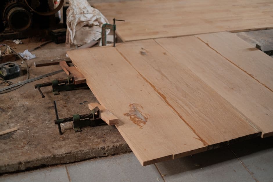
Second pass: the panel gets crosscut into slices
Next the flattened panel is laid flat and cut across, perpendicular to the first glue line. Each cut yields a slice of a set thickness, usually equal to the width of a finished row in the pattern. This is where kerf shows up again: between adjacent slices you lose the width of the blade, and the diagram builds that into the slice's own stated width.
If the diagram shows an inlay, that is a slice cut from a separate, pre-assembled panel and set into a slot cut in the main one. This is how accent lines and borders get made, and the diagram flags the inlay step with a note on which panel it comes from.
Final assembly: rows, flip, and mirror
Slices get arranged into rows and glued a second time, and this final glue-up is what produces the end-grain surface: the grain points up, and the end of every slice is visible across the full thickness. Two flags show up on each row in the diagram:
| Flag | What it means | Why it matters |
|---|---|---|
| flip | the row is turned over along its own axis | changes which face of the species meets the next row, which is how a symmetric pattern gets built |
| mirror | the strip order within the row is reversed | reverses the species sequence in that row front to back |
Without these two flags, almost nothing more complex than a plain checkerboard is buildable. Alternating flips and mirrors is what turns identical slices into a chevron, a herringbone, or a diagonal grid.
What to do with the numbers next to the diagram
Next to each step, the diagram prints thickness, width, and cut count, and that is not reference material, it is a direct instruction for the saw: set the fence to the stated dimension and make the stated number of cuts at that thickness in a row, with no eyeballing between blanks. Get a row number wrong or swap flip for mirror, and the next part lands in the wrong spot, which usually means reglueing the whole block.
The panel widths at every step already account for kerf and allowances, and species for neighboring strips are worth choosing with shrinkage and compatibility in mind, so the joints between rows do not open up after a season. The full diagram for your own design, with row numbers and exact dimensions for every slice, can be built and printed directly in the Endgrain Studio editor.